Physical Circuits
Physical circuits are constructed of real, physical devices. Physical circuits can be inspected, tested, and modified. They consume electric power when energized, and they can function properly and do some meaningful work, or they can malfunction and create serious hazards to health and property. Even small circuits that are quickly and easily constructed still take time and money to build, and they can take a very long time to perfect.
Model Circuits
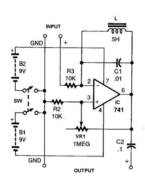
Model circuits are built on a computer and simulate the workings of the circuit, which allows for testing before the physical circuit is created. Engineers learned long ago that prior to building even the simplest circuit a document showing all pertinent construction details is indispensable. Serving much the same purpose as blueprints for a building, a circuit schematic shows all devices in the circuit, and all signal and power connections between the devices (shown in Fig. 1 below). A schematic can be sketched, analyzed, debated, re-sketched, and iterated as many times as needed before the more cost and time intensive task of building a real circuit begins. Once computers became available, it didn’t take engineers long to realize that if a circuit schematic could be “captured” in a computer program, it could be simulated to any degree of accuracy before it was constructed. And indeed, it could well be argued that circuit simulators represent the most useful and powerful application of computers that has ever been found.

Nearly all physical circuits start out as models on a computer, defined in a Computer Aided Design (or CAD) tool. By constructing a computer-based model, engineers can quickly and easily study all aspects of a given circuit before building it, saving countless hours and expenses. But it is important to always bear in mind that a circuit model is not a real circuit; it is only a model, a “what if”, and the model is only as good as the assumptions used by the programmers who wrote the CAD tool. The CAD tools help to improve the correctness and quality of designs. Modern circuit models use one of two definitional forms: schematics, or pictorial representations of circuit devices and interconnecting wires; and hardware definition languages (HDL), or text-based descriptions of devices and interconnecting wires. HDLs can be used to design anything from individual function modules to multichip digital systems. Both forms will be examined in later modules.
Important Ideas
- Physical circuits can be inspected, tested, and modified. They consume electric power when energized, and they can function properly and do some meaningful work, or they can malfunction and create serious hazards to health and property.
- Once computers became available, it didn’t take engineers long to realize that if a circuit schematic could be “captured” in a computer program, it could be simulated to any degree of accuracy before it was constructed.
