Digital Circuits
This section will give you a brief overview of digital circuits that will be expanded upon later in this chapter. Digital circuits function on two levels that when put together create the desired outcome.
A digital circuit is constructed of a power supply, devices, and conduction nets. Some nets provide circuit inputs from the “outside world”; in a schematic, these input nets are generally shown entering the left side of component and/or the overall circuit. Other nets provide circuit outputs to the outside world; these nets are generally shown exiting the schematic on the right. In the sample schematic in Fig. 1 below, circuit components are shown as arbitrary shapes, nets are shown as lines, and inputs and outputs are denoted by connector symbols.

A digital circuit requires a power supply to provide a constant and stable source of electric power to all devices. As discussed above, electric power is derived from the basic electrical forces that charged particles exert on one another—namely, electrons are repelled by other electrons, and attracted to more electrically positive areas where there are relatively fewer electrons. The vast majority of charged particles are found in ordinary matter bound in electrically neutral atomic structures (that is, most particles are found in structures that have an equal number of positive and negative particles). Some electrically neutral conducting materials (like metals) contain electrons that are not so tightly bound to their host atoms. If a voltage source is applied to these materials, the lightly bound electrons will move away from the concentrated source of electrons on the negative side of the supply towards the electrically positive side of the supply. A “power supply” in a digital circuit provides a local, contained imbalance of electrons that provides a voltage source that can do useful work, such as transmitting information through a conductor from one device to another. A digital circuit allows a controlled flow of electrons from of the negative to positive side of the power supply, but only via the paths designed into the circuit. As electrons flow to and from the devices in a given circuit, they can change device properties in useful ways.
In a digital circuit, power supply voltage levels are constrained to two distinct values—“logic high voltage” (called LHV or Vdd) and “logic low voltage” (called LLV or GND). The GND node in any circuit is the universal reference voltage against which all other voltages are measured (in modern digital circuits, GND is typically the lowest voltage in the circuit). In a schematic, it is often difficult to show lines connecting all GND nodes; rather, any nodes labeled GND are assumed to be connected into the same node. Often, a downward pointing triangle symbol is attached to a GND node in addition to (or instead of) the GND label. The Vdd node in a digital circuit is typically the highest voltage, and all nodes labeled Vdd are tied together into the same node. Vdd may be thought of as the “source” of positive charges in a circuit, and GND may be thought of as the “source” of negative charges in a circuit. In modern digital systems, Vdd and GND are separated by anywhere from 1 to 5 volts. Older or inexpensive circuits typically use 5 volts, while newer circuits use 1-3 volts.
In digital circuits, the Vdd and GND voltages are used not only to supply electric power to circuit devices; they are used to represent information as well.
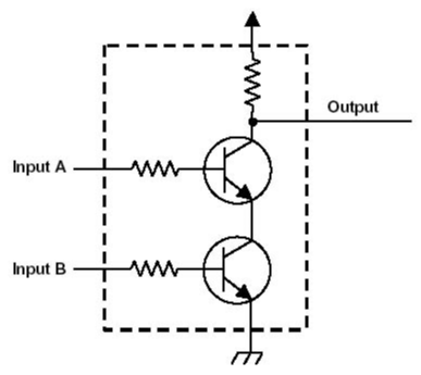
The most basic digital devices are called gates. The function of gates is to allow or delay “gating“ the flow of digital information. In general, a gate has one or more inputs and produces an output (more on that later). AND, OR, and NOT are three basic types of gates. We will discuss them in future sections. Figure 2 shows the schematic of a basic logic gate.

Important Ideas
- Digital circuits are composed of power supply, devices, and conduction nets. Some nets provide the circuit with information from the outside world while other nets take information from the circuit and provide it to the outside world.
- Digital circuit power supply voltages are constrained to two distinct values Logic High and Logic Low which are shortened to Vdd and GND. These two values also represent the transfer of information around the circuit.
- The most basic digital device is called a gate. The function of gates is to allow or slow that flow of information.
